LoRa
- Architecture
- Standard build
- E22 900M30S LoRa module
- E22-900T22S LoRa module (on Waveshare hat, SKU 16807)
- Raspberry Pi
- Optimizing radio parameters experiment
- LG01: OpenWrt gateway
- Meshtastic
Architecture
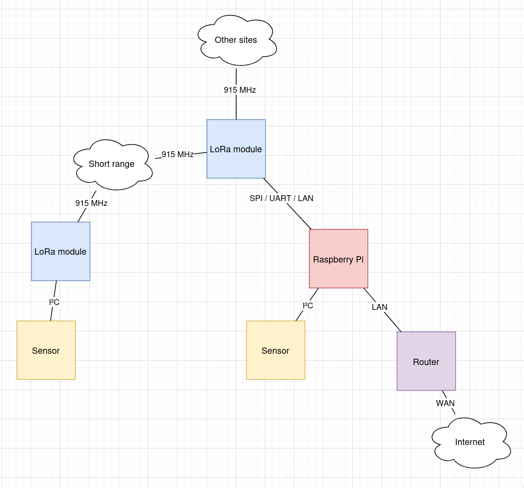
Standard build
A Raspberry Pi
Gathers data from sensors
- I²C mostly, such as ADS1115
Broadcasts over LoRa (and the Internet via the RPi Ethernet port to the LAN)
- The LG01 can be used by the Pi as a device with which to broadcast over LoRa, possibly via the LAN, whereas other modules will need to be connected via SPI or UART.
Has a lightweight web app, which:
Provides a generic UI with which to configure sensors at a particular site.
Takes readings from those sensors, and stores in a TSD such as RRDtool.
Might provide an HTML5 dashboard of current readings along with charts of historical data.
Might provide that same data via an API so that a native phone app can present that same data.
Node-RED might provide a no-coding method of setting up alerts when readings are outside of nominal.
Shane suggested Wee WX.
Raspberry Pi setup
Manual option (rather than "Imager"), 64-bit, Lite from here.
xzcat /media/files/software/Raspberry-Pi/2025-05-13-raspios-bookworm-arm64-lite.img.xz | dd iflag=fullblock of=/dev/sdZ bs=8M oflag=direct status=progress
The 2025-05-13 image does not enable the serial port nor SSH initially (WTF!?) and requires an HDMI monitor and a keyboard to set up.
- Choose a hostname, so that multiple SBCs on the network don't all call
themselves
raspberrypi. Suggestpi-Z, whereZisa,b,c, etc. (a serial number). - Enable the SSH server. Use
PasswordAuthentication nofor security later on once keys have been installed. - Enable console on the serial port. The default will be 115,200 baud.
- Enable automatic loading of the SPI module. Required for LoRa module.
- Enable automatic loading of the I2C module. Required for sensors.
-
dpkg-reconfigure tzdata - Follow Meshtastic on Linux installation instructions at https://meshtastic.org/docs/hardware/devices/linux-native-hardware/?os=raspbian
I used this in config.d:
# MeshAdv-Pi E22-900M30S
# https://github.com/chrismyers2000/MeshAdv-Pi-Hat
Lora:
  Module: sx1262
  # These numbers correspond to GPIOx labels on the Pi header pinout, so `21`
  # means `GPIO21`.
  CS:     8
  IRQ:   16
  Busy:  19
  Reset:  5
  TXen:  13
  RXen:   6
  DIO3_TCXO_VOLTAGE: true
Next: Set up.
Bluetooth
sed 's/BLUETOOTH_ENABLED=1/BLUETOOTH_ENABLED=0/' /etc/default/bluetooth
# I have a feel that the "primary" UART at /dev/ttyS0 is the one that
# varies its baud rate as the VPU clock changes.  Perhaps the real UART is
# used to interface with the bluetooth chip?
# https://www.raspberrypi.com/documentation/computers/configuration.html#configuring-uarts
systemctl disable hciuart
# Add disable-bt to the device tree, and reboot.
# /dev/serial0 seems to indicate the "primary" UART, which is the reliable
# (PL011) UART only if bluetooth is diabled with dtoverlay=disable-bt in
# config.txt.
Not using WiFi
systemctl disable wpa_supplicant.service
I2C
install i2c-tools
CLI
i python3-pip
Shutdown button
If a Pi has been shut down, bridging
GPIO3andGNDwill cause it to start up.Adding
dtoverlay=gpio-shutdown(to/boot/firmware/config.txt) will use the same pin (GPIO3) to shut down gracefully.Sadly,
GPIO3isSCL1, so unless I2C is not in use, or the I2C pins are remapped then a different pin must be used and specified:dtoverlay=gpio-shutdown,gpio_pin=21.The internal pull-ups are ~ 50 kΩ. Hopefully a 1 kΩ will get it close enough to 0 V to work, but still providing a little insurance against GPIO21 being accidentally configured to drive high.
E22 900M30S LoRa module
- https://www.cdebyte.com/pdf-down.aspx?id=3513
- Up to 62.5 kbps in LoRa mode
- SX1262
- 1W max
E22-900T22S LoRa module (on Waveshare hat, SKU 16807)
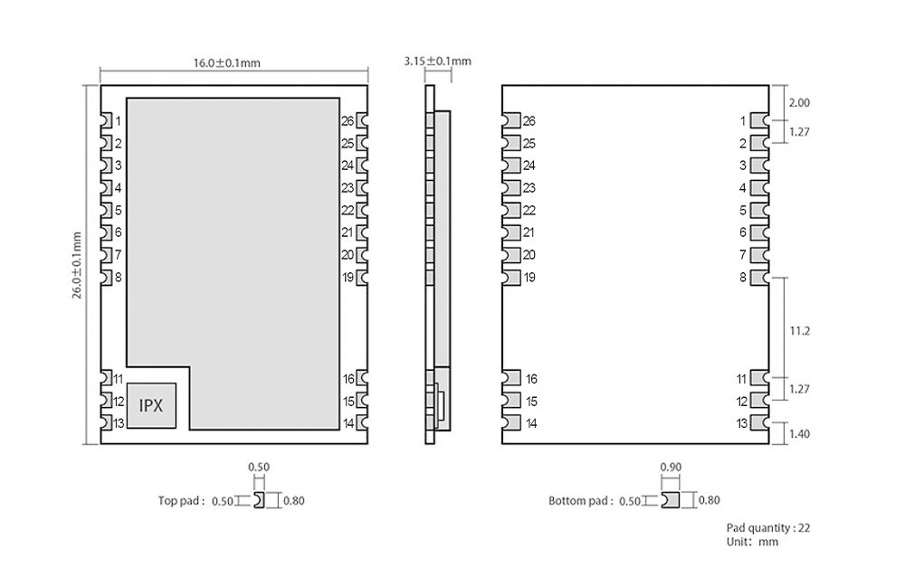
| Pin | Purpose |
|---|---|
| 1 | NRST, Reset, active low. |
| 2 | GND |
| 3 | GND |
| 4 | NC |
| 5 | NC |
| 6 | NC |
| 7 | NC |
| 8 | GND |
| 11 | GND |
| 12 | ANT |
| 13 | GND |
| 14 | GND |
| 15 | GND |
| 16 | GND |
| 19 | GND |
| 20 | M0, Together with M1, define the "mode" (0-3). These "bits" are 0 when the jumper grounds the pin. |
| 21 | M1 |
| 22 | RXD |
| 23 | TXD |
| 24 | AUX |
| 25 | VCC, 2.5 - 5.2 V |
| 26 | GND |
The RXD and TXD module pins are not connected to the I/O header, but
instead to a CP2102 USB-to-serial bridge.
I/O header traces
- +5V
- GND
- P7 GPIO4
- TXD to jumpers
- RXD to jumpers
- P2 GPIO27
- P3 GPIO22
The jumpers can be set in one of three positions (A, B, or C):
- A: The RXD and TXD from the CP2102 are connected to the LoRa module, or:
- B: RXD and TXD from the I/O header are connected to the LoRa module, or:
- C: RXD and TXD from CP2102 are connected to RXD and TXD on the I/O header
UART hats not supported by Meshtastic.
Raspberry Pi
Arguments against the Raspberry Pi:
It's not the most power efficient solution in most cases.
It's expensive compared to equivalent solutions.
The SoC requires a closed source binary blob in order to operate.
Arguments for:
The software is supported for an awful long time.
It has mindshare.
Marty has some stock on hand.
At least one site already has one in service.
Optimizing radio parameters experiment
Precis: For a given set of radio parameters, send pings and keep track of the number of echoes received.
Two radios: master and slave.
The slave services requests to change parameters such as transmit power.
The master is controlled by a full-fat system with an accurate clock (the orchestrator).
Process:
The orchestrator waits until midnight then begins walking through a list of sets of parameters.
The parameters are applied to both the master and slave radios.
The orchestrator then makes a ping request every minute for 24h and makes a record of whether a response was received or not, along with the RSSI and other parameters such as SNR and frequency error.
The ping request payload should include a random number that is verified upon receipt (this can be coded on the orchestrator) as an assurance that the echo response is to the most recent request and not to a previous response, or noise, or a response to a ping request by another station on the network.
The deliverable is a table like this (for each set of parameters):
When RSSI SNR 2025-07-04T23:02:57+12:00 -93 3.00 2025-07-04T23:02:58+12:00 ? ? ..though it might be best summarised as the packet loss ratio for each set of parameters.
It will be interesting to see if the time of day (or day of the week) affects deliverability.
LG01: OpenWrt gateway
It's not immediately obvious what the purpose of the LG01 is. It's not an OTS solution, so it's probably intended for whatever it can be used for. The Raspberry Pi is easier to work with as a system at the heart of a site installation, so the LG01 on hand could be gainfully under-utilised by reading sensor data (via the exposed IOs) and providing the readings to the Raspberry Pi. The Arduino Unos with LoRa shields can accomplish the same task via the UART, but the LG01 could do so via the LAN, or even over the Internet.
Installing packages
- Go to the repository.
- Download the
.ipkof interest. scp example.ipk LG01:/tmp/.opkg install example.ipkon the LG01.
It is not practical to install additional packages with opkg update. The web
server that hosts the package repository has a recent TLS certificate and the
OpenWrt build from 2017 does not include that certificate (wget returns exit
code 5). After trying to install the certificate, I instead tried to
configure a proxy (option http_proxy in opkg.conf), with no luck.
Flashing the Arduino
The virtual port appears in the Arduino IDE (is this some kind of zeroconf magic?), but attempts to upload to it are met with:
Resetting the board
Failed to reset the board, upload failed
Failed uploading: uploading error: exit status 1
Sketches (.hex files) may be uploaded manually via the web UI at Sensor,
Flash MCU.
This was seen in ps output when uploading a sketch:
avrdude -c linuxgpio -C /etc/avrdude.conf -p m328p -U lfuse:w:0xFF:m -U hfuse:w:0xDE
It should also be possible to upload with:
avrdude -c linuxgpio -C /etc/avrdude.conf -p m328p -Uflash:w:/tmp/LoRa-chat.ino.hex
..but this causes:
avrdude: AVR device not responding
avrdude: initialization failed, rc=-1
         Double check connections and try again, or use -F to override
         this check.
..so back to the web UI then.
EEPROM
The web UI seems to erase the EEPROM whenever a new sketch is uploaded.
Serial link from the router (MIPS CPU) to the Arduino
On the router, /dev/ttyATH0 is connected to the Arduino UART:
screen /dev/ttyATH0 115200
The screen package was installed (along with ss and ser2net).